Mitigating Application Threats with BIG-IP Next WAF
Overview of BIG-IP Next In today's modern world where the digital landscape is continuously evolving and security threats are becoming more sophisticated, the need for a robust and adaptive security solution is essential. BIG-IP Next is a next-generation solution which is setting a new standard for safeguarding your digital assets, protecting your applications, and empowering enterprises with the highest security efficacy.BIG-IP Next is the modernized solution optimized to simplify operations, enhance performance, and strengthen security. As per the official website, BIG-IP Next simplifies day-to-day ADC operations and accelerates application time-to-market through automation so that you can focus more on getting your apps online. BIG-IP Next’s modern, highly scalable software architecture is designed for maximum resiliency to support vast, dynamic application portfolios and their most complex traffic management and security policies, ensuring that applications are always available to end users. BIG-IP Next also provides deep insights into your application health, network performance, traffic patterns, and security threats to improve business decision-making. For a quick overview of BIG-IP Next and how the next-generation attributes can help you with your existing or new deployments, check out the video below. Here are some of the key capabilities that you can checkout and learn how you can mitigate app threats and security complexity with BIG-IP Next WAF: 1. Deploy HTTPS application with WAF Protection The first step in protecting your applications starts with onboarding your application in BIG-IP Next instance and creating a WAF security policy as per application requirements. Finally creating load balancers and applying the above-created WAF policies. Next, users can monitor the application traffic by navigating to their respective security dashboards and take necessary steps as per security insights. For more details, see this video. 2. Create and Manage Security Policies Sometimes creating security policies can be a time-consuming job, and BIG-IP Next has made this user-friendly for creating and managing security policies from a centralized UI. Users can create, delete or update their existing policies in fewer steps and can apply them directly to the applications, thereby decreasing the application delivery time to market. You can check out the video below for more details. 3. Create Security Policies using Templates One more advantage of BIG-IP Next is the support for creating security policies using templates and it’s just a one-click action using 'F5 BIG-IP Next’. Users can make use of default templates and protect their applications with zero effort, for ex. Using the Violation Rating Template. For more information, check below video. 4. Security Policy Migration Going through existing BIG-IP security policies and then creating the same ones in BIG-IP Next solution can be time-consuming. This is made easy so that users can migrate their security policy from 'F5 Advanced WAF' to 'F5 BIG-IP Next WAF' in a simple manner. With fewer steps, you can have your entire WAF security posture up without going through the rough step of creating them from scratch. Please refer to the video below for more insights. 5. Signatures and Threat Campaigns Update Regular update of attack signatures and threat campaigns is a vital step in safeguarding your applications against the latest attacks. This process is super easy using ‘F5 BIG-IP Next’ so that applications can mitigate them without the need for downtime. For step-by-step procedure to update signatures and threat campaigns, please check the video below. You can also check out the demo link below for detailed insights of how BIG-IP Next WAF enables the migration of apps and policies between BIG-IP TMOS and BIG-IP Next. The demo also shows how to deploy new web applications with WAF security policies included within BIG-IP Next Central Manager and finally how to analyze and respond to security incidents within the Next WAF dashboard. Reference links What is BIG-IP Next? | DevCentral Getting Started with BIG-IP Next: Fundamentals | DevCentral https://www.f5.com/products/big-ip-services/big-ip-next 74Views0likes0Comments
What is BIG-IP Next?
BIG-IP Next LTM and BIG-IP Next WAF hit general availability back in October, and we hit the road for a tour around North America for its arrival party! Those who attended one of our F5 Academy sessions got a deep-dive presentation into BIG-IP Next conceptually, and then a lab session to work through migrating workloads and deploying them. I got to attend four of the events and discuss with so many fantastic community members what's old, what's new, what's borrowed, what's blue...no wait--this is no wedding! But for those of us who've been around the block with BIG-IP for a while, if not married to the tech, we definitely have a relationship with it, for better and worse, right? And that's earned. So any time something new, or in our case "Next" comes around, there's risk and fear involved personally. But don't fret. Seriously. It's going to be different in a lot of ways, but it's going to be great. And there are a crap-ton (thank you Mark Rober!) of improvements that once we all make it through the early stages, we'll embrace and wonder why we were even scared in the first place. So with all that said, will you come on the journey with me? In this first of many articles to come from me this year, I'll cover the high-level basics of what is so next about BIG-IP Next, and in future entries we'll be digging into the tech and learning together. BIG-IP and BIG-IP Next Conceptually - A Comparison BIG-IP has been around since before the turn of the century (which is almost old enough to rent a car here in the United States) and this year marks the 20 year anniversary of TMOS. That the traffic management microkernel (TMM) is still grokking like a boss all these years later is a testament to that early innovation! So whereas TMOS as a system is winding down, it's heart, TMM, will go on (cue sappy Celine Dion ditty in 3, 2, 1...) Let's take a look at what was and what is. With TMOS, the data plane and control plane compete for resources as it's one big system. With BIG-IP, the separation of duties is more explicit and intentionally designed to scale on the control plane. Also, the product modules are no longer either completely integrated in TMM or plugins to TMM, but rather, isolated to their own container structures. The image above might convey the idea that LTM or WAF or any of the other modules are single containers, but that's just shown that way for brevity. Each module is an array of containers. But don't let that scare you. The underlying kubernetes architecture is an abstraction that you may--but certainly are not required to--care about. TMM continues to be its awesome TMM self. The significant change operationally is how you interact with BIG-IP. With TMOS, historically you engage directly with each device, even if you have some other tools like BIG-IQ or third-party administration/automation platforms. With BIG-IP Next, everything is centralized on Central Manager, and the BIG-IP Next instances, whether they are running on rSeries, VELOS, or Virtual Edition, are just destinations for your workloads. In fact, outside of sidecar proxies for troubleshooting, instance logins won't even be supported! Yes, this is a paradigm shift. With BIG-IP Next, you will no longer be configuration-object focused. You will be application-focused. You'll still have the nerd-knobs to tweak and turn, but they'll be done within the context of an application declaration. If you haven't started your automation journey yet, you might not be familiar with AS3. It's been out now for years and works with BIG-IP to deploy applications declaratively. Instead of following a long pre-flight checklist with 87 steps to go from nothing to a working application, you simply define the parameters of your application in a blob of JSON data and click the easy button. For BIG-IP Next, this is the way. Now, in the Central Manager GUI, you might interact with FAST templates that deliver a more traditional view into configuring applications, but the underlying configuration engine is all AS3. For more, I hosted aseries of streams in December to introduce AS3 Foundations, I highly recommend you take the time to digest the basics. Benefits I'm Excited About There are many and you can read about them on the product page on F5.com. But here's my short list: API-first. Period. BIG-IP had APIs with iControl from the era before APIs were even cool, but they were not first-class citizens. The resulting performance at scale requires effort to manage effectively. Not only performance, but feature parity among iControl REST, iControl SOAP, tmsh, and the GUI has been a challenge because of the way development occurred over time. Not so with BIG-IP Next. Everything is API-first, so all tooling is able to consume everything. This is huge! Migration assistance. Central Manager has the JOURNEYS tool on sterroids built-in to the experience. Upload your UCS, evaluate your applications to see what can be migrated without updates, and deploy! It really is that easy. Sure, there's work to be done for applications that aren't fully compatible yet, but it's a great start. You can do this piece (and I recommend that you do) before you even think about deploying a single instance just to learn what work you have ahead of you and what solutions you might need to adapt to be ready. Simplified patch/upgrade process. If you know, you know...patches are upgrades with BIG-IP, and not in place at that. This is drastically improved with BIG-IP Next! Because of the containerized nature of the system, individual containers can be targeted for patching, and depending on the container, may not even require a downtime consideration. Release cycle. A more frequent release cadence might terrify the customers among us that like to space out their upgrades to once every three years or so, but for the rest of us, feature delivery to the tune of weeks instead of twice per year is an exciting development (pun intended!) Features I'm Excited About Versioning for iRules and policies. For those of us who write/manage these things, this is huge! Typically I'd version by including it in the title, and I know some who set release tags in repos. With Central Manager, it's built-in and you can deploy iRules and polices by version and do diffs in place. I'm super excited about this! Did I mention the API? On the API front...it's one API, for all functionality. No digging and scraping through the GUI, tmsh, iControl REST, iControl SOAP, building out a node.js app to deploy a custom API endpoint with iControl LX, if even possible with some of the modules like APM or ASM. Nope, it's all there in one API. Glorious. Centralized dashboards. This one is for the Ops teams! Who among us has spent many a day building custom dashboards to consume stats from BIG-IPs across your org to have a single pane of glass to manage? I for one, and I'm thrilled to see system, application, and security data centralized for analysis and alerting. Log/metric streaming. And finally, logs and metrics! Telemetry Streaming from the F5 Automation Toolchain doesn't come forward in BIG-IP Next, but the ideas behind it do. If you need your data elsewhere from Central Manager, you can set up remote logging with OpenTelemetry (see the link in the resources listed below for a first published example of this.) There are some great features coming with DNS, Access, and all the other modules when they are released as well. I'll cover those when they hit general availability. Let's Go! In the coming weeks, I'll be releasing articles on installation and licensing walk-throughs for Central Manager and the instances, andcontent from our awesome group of authors is already starting to flow as well. Here are a few entries you can feast your eyes on, including an instance Proxmox installation: For the kubernetes crowd, BIG-IP Next CNF Solutions for RedHat Openshift Installing BIG-IP Next Instance on Proxmox Remote Logging with BIG-IP Next and OpenTelemetry Are you ready? Grab a trial licensefrom your MyF5 dashboard and get going! And make sure to join us in the BIG-IP Next Academy group here on DevCentral. The launch team is actively engaged there for next-related questions/issues, so that's the place to be in your early journey! Also...if you want the ultimate jump-start for all things BIG-IP Next, join usatAppWorld 2024 in SanJose next month!3.6KViews17likes5CommentsCreate F5 BIG-IP Next Instance on Proxmox Virtual Environment
If you are looking to deploy a F5 BIG-IP Next instance on Proxmox Virtual Environment (henceforth referred to as Proxmox for the sake of brevity), perhaps in your home lab, here's how: First, download the BIG-IP Next OVA File from MyF5 Downloads. Copy the OVA file to your Proxmox host. I am using SCP in the example below. local $ scp BIG-IP-Next-20.0.1-2.139.10+0.0.136.ovf root@proxmox:~/ On the Proxmox host, extract the contents in the OVA file: proxmox $ cd ~/ proxmox $ tar -xvf BIG-IP-Next-20.0.1-2.139.10+0.0.136.ova BIG-IP-Next-20.0.1-2.139.10+0.0.136.ovf BIG-IP-Next-20.0.1-2.139.10+0.0.136.mf BIG-IP-Next-20.0.1-2.139.10+0.0.136.cert BIG-IP-Next-20.0.1-2.139.10+0.0.136-disk1.vmdk Then, run the command below to create a virtual machine (VM) from the extracted OVF file. <vm_id> should be an unused ID on Proxmox. # qm importovf <vm_id> BIG-IP-Next-20.0.1-2.139.10+0.0.136.ovf local-lvm proxmox $ qm importovf 112 BIG-IP-Next-20.0.1-2.139.10+0.0.136.ovf local-lvm Logical volume "vm-112-disk-0" created. transferred 0.0 B of 80.0 GiB (0.00%) transferred 819.2 MiB of 80.0 GiB (1.00%) transferred 1.6 GiB of 80.0 GiB (2.00%) <output truncated> transferred 80.0 GiB of 80.0 GiB (100.00%) transferred 80.0 GiB of 80.0 GiB (100.00%) You should now see a new VM created on the Proxmox GUI. Before starting the VM, we need to attach a few hardware components to the VM: a Network Device for the management interface one or more additional Network Devices for the data plane interfaces (e.g. internal and external). Note that the data plane Network Devices must be of VirtIO model Optionally, you could also configure CLI access with the following instructions Finally, start the VM. This will take a few minutes. If CLI access is available, open up the console and run kubectl get pods until you can see all pods are ready. The BIG-IP Next VM is now ready to be onboarded per instructions found here.1.5KViews6likes2CommentsHow to get a F5 BIG-IP VE Developer Lab License
(applies to BIG-IP TMOS Edition) To assist DevOps teams improve their development for the BIG-IP platform, F5 offers a low cost developer lab license.This license can be purchased from your authorized F5 vendor. If you do not have an F5 vendor, you can purchase a lab license online: CDW BIG-IP Virtual Edition Lab License CDW Canada BIG-IP Virtual Edition Lab License Once completed, the order is sent to F5 for fulfillment and your license will be delivered shortly after via e-mail. F5 is investigating ways to improve this process. To download the BIG-IP Virtual Edition, please log into downloads.f5.com (separate login from DevCentral), and navigate to your appropriate virtual edition, example: For VMware Fusion or Workstation or ESX/i:BIGIP-16.1.2-0.0.18.ALL-vmware.ova For Microsoft HyperV:BIGIP-16.1.2-0.0.18.ALL.vhd.zip KVM RHEL/CentoOS: BIGIP-16.1.2-0.0.18.ALL.qcow2.zip Note: There are also 1 Slot versions of the above images where a 2nd boot partition is not needed for in-place upgrades. These images include_1SLOT- to the image name instead of ALL. The below guides will help get you started with F5 BIG-IP Virtual Edition to develop for VMWare Fusion, AWS, Azure, VMware, or Microsoft Hyper-V. These guides follow standard practices for installing in production environments and performance recommendations change based on lower use/non-critical needs fo Dev/Lab environments. Similar to driving a tank, use your best judgement. DeployingF5 BIG-IP Virtual Edition on VMware Fusion Deploying F5 BIG-IP in Microsoft Azure for Developers Deploying F5 BIG-IP in AWS for Developers Deploying F5 BIG-IP in Windows Server Hyper-V for Developers Deploying F5 BIG-IP in VMware vCloud Director and ESX for Developers Note: F5 Support maintains authoritativeAzure, AWS, Hyper-V, and ESX/vCloud installation documentation. VMware Fusion is not an official F5-supported hypervisor so DevCentral publishes the Fusion guide with the help of our Field Systems Engineering teams.74KViews13likes143CommentsGetting Started with BIG-IP Next: Configuring Instance High Availability
With BIG-IP classic, there are a lot of design choices to make and steps on both systems to arrive at an HA pair. With BIG-IP Next, this is simplified quite a bit. Once configured, the highly available pair is treated by Central Manager as a single entity. There might be alternative options in the future, but as of version 20.1, HA for instances is active/standby only. In this article, I'll walk you through the steps to configure HA for instances in the Central Manager GUI. Background and Prep Work I set up two HA systems in my preparation for this article. The first had dedicated interfaces for the management interface, the external and internal traffic interfaces, and the HA interface. So when configuring the virtual machine, I made sure each system had four NICs. For the second, I merged all the non-management interfaces on a single NIC and used vlan tagging, so those systems had two NICs. In my lab that looks like this: The IP addressing scheme in my lab is shown below. First the four NIC system: 4-NIC System next-4nic-a next-4nic-b floating mgmt 172.16.2.152/24 172.16.2.153/24 172.16.2.151/24 cntrlplane ha (vlan 245) 10.10.245.1/30 10.10.245.2/30 NA dataplane ha (int 1.3) 10.0.5.1/30 10.0.5.2/30 NA dataplane ext (int 1.1) 10.0.2.152/24 10.0.2.153/24 10.0.2.151/24 dataplane int (int 1.2) 10.0.3.152/24 10.0.3.153/24 10.0.3.151/24 And now the two NIC system: 2-NIC System next-2nic-a next-2nic-b floating mgmt 172.16.2.162/24 172.16.2.163/24 172.16.2.161/24 cntrlplane ha (vlan 245) 10.10.245.5/30 10.10.245.6/30 NA dataplane ha (vlan 50) 10.0.5.5/30 10.0.5.6/30 NA dataplane ext (vlan 30) 10.0.2.162/24 10.0.2.163/24 10.0.2.161/24 dataplane int (vlan 40) 10.0.3.162/24 10.0.2.163/24 10.0.3.161/24 Beyond the self IP addresses for your traffic interfaces, you'll need additional IP addresses for the floating address, the control-plane HA sub-interfaces (which are created for you), and teh data-plane HA interfaces. Before proceeding, make sure you have a plan for network segmentation and addressing similar to above, you've installed two like instances, and that one (and only one) of them is licensed. Configuration This walk through is for the 2-NIC system shown above, but the steps are mostly the same. First, login to Central Manager, and click on Manage Instances. Click on the standalone mode for the system you want to be active initially in your HA pair. For me, that's next-2nic-a. (You can also just click on the system name and then select HA in the menu, but this saves a click.) In the pop-up dialog, select Enable HA. Read the notes below to make sure your systems are ready to be paired. On this screen, a list of available standalone systems will populate. Click the down arrow and select your second system, next-2nic-b in my case. Then click Next. On this next prompt, you'll need to create two vlans, one for the control plane and one for the data plane. The control plane mechanics are taken care of for you and you don't need to plan connectivity other than to select an available vlan that won't conflict with anything else in your system. For the data plane, you need to have a dedicated vlan and/or interface set aside. Click Create VLAN for the control plane. Name and tag your vlan. In my case I used cp-ha as my vlan name and tag 245. Click Done. Now click Create VLAN for the data plane. Because I'm tagging all networks on the 2-NIC system, my own interface is 1.1. So I named my data plan vlan dp-ha, set the tag to 50, selected interface 1.1, and clicked Done. Now that both HA VLANs have been created, click Next. On this screen, you'll name your HA pair system. This will need to be unique from other HA pairs, so plan accordingly. I named mine next-ha-1, but that's generic and unlikely to be helpful in your environment. Then set your HA management IP, this is how Central Manager will connect to the HA pair. You can enable auto-failback if desired, but I left that unchecked. For the HA Nodes Addresses, I referenced my addressing table posted at the top of this article and filled those in as appropriate. When you get those filled out, click Next. Now you'll be presented with a list of your traffic VLANs. On my system I have v102-ext and v103-int for my external and internal networks. First, I clicked v102-ext. On this screen you'll need to add a couple rows so you can populate the active node IP, the standby node IP, and the floating IP. The order doesn't matter, but I ordered them as shown, and again referenced my addressing table. Once populated, click Save. That will return you to this screen, where you'll notice that v102-ext now has a green checkbox where the yellow warning was. Now click into your other traffic VLAN (v103-int in my case) if applicable to your environment or skip this next step. This is a repeat of the external traffic network for the internal traffic network. I referenced my address table one more time and filled the details out as appropriate, then clicked Save. Make sure that you have green checkboxes on the traffic VLANs, then click Next. Review the summary of the HA settings you've configured, and if everything looks right, click Deploy to HA. On the "are you sure?" dialog where you're prompted to confirm your deployment, click Yes, Deploy. You'll then see messaging at the top of the HA configuration page for the instance indicating that HA is being created. Also note that the Mode on this page during creation still indicates standalone. Once the deployment is complete, you'll see the mode has changed to HA and the details for your active and standby nodes are provided. Also present here is the Enable automatic failover option, which is enabled by default. This is for software upgrades. If left enabled, the standby unit will be upgraded first, a failover will be executed, and the the remaining system will be upgraded. If in your HA configuration you specified auto-failback, then after the second system is upgraded there will be another failover executed to complete the process. And finally, as seen in the list of instances, there are three now instead of four, with next-ha-1 taking the place of next-2nic-a and next-2nic-b from where we started. Huzzah! You now have a functioning BIG-IP Next HA pair. After we conclude the "Getting Started" series, we'll start to look at the benefits of automation around all the tasks we've covered so far, including HA. The click-ops capabilities are nice to have, but I think you'll find the ability to automate all this from a script or something like an Ansible playbook will really start to drive home the API-first aspects of Next.403Views1like1CommentGetting Started with BIG-IP Next: Licensing Instances in Central Manager
This article assumes that the license was not applied during the initial instance setup. Download the JSON Web Token from MyF5 I don't have a paid license, so I'm going to use my trial license available at MyF5. Your mileage may vary here. Go to my products & plans, trials, and then in the my trials listing (assuming you've requested/received one) click BIG-IP Next. Click downloads and licenses (note, however, the helpful list of resources down in guides and references). You can just copy your JSON web token, but I chose to download. Install the Token Login to Central Manager and click manage instances. Click on your new unlicensed instance. In the left-hand menu at the bottom, click License. Click activate license. We already downloaded our token, so after reviewing the information, click next. Note that I made sure that my Central Manager has access to the licensing server and the steps covered in this article assume the same. If you've managed classic BIG-IP licenses, copying and pasting dossiers to get licenses should be a well-understood process. On this screen, paste your token into the box, give it a name, and click activate. After a brief interrogation of the licensing server, you should now have a healthy, licensed, BIG-IP Next Instance! Resources How to: Manage BIG-IP Next instance licenses405Views0likes6Comments
Converting a BIG-IP Maintenance Page iRule to Distributed Cloud using App Stack
If you are familiar with BIG-IP, you are probably also familiar with its flexible and robust iRule functionality. In fact, I would argue that iRules makes BIG-IP the swiss-army knife that it is. If there is ever a need for advanced traffic manipulation, you can usually come up with an iRule to solve the problem. F5 Distributed Cloud (XC) has its own suite of tools to help in this regard. If you need to do some sort of traffic manipulation/routing you can usually handle that with Service Policies or simply using Routes. Even with these features, however, there are going to be some cases where iRule functionality from the BIG-IP cannot be reproduced directly in XC. When this happens, we switch to using App Stack, which is XC’s version of a swiss army knife. In this article, I wanted to walk through an example of how you can leverage XC's App Stack for a specific iRule conversion use case: Displaying a Custom Maintenance Page when all pool members are down. For reference, here is the iRule: when LB_FAILED { if { [active_members [LB::server pool]] == 0 } { if { ([string tolower [HTTP::host]] contains "example.com")} { if { [HTTP::uri] ends_with "SystemMaintenance.jpg" } { HTTP::respond 200 content [ifile get "SystemMaintenance.jpg"] "Content-Type" "image/jpg" } else { HTTP::respond 200 content "<!DOCTYPE html> <html lang="en"> <head> <title>System Maintenance</title> <style type="text/css"> .base { font-family: 'Tahoma'; font-size: large; } </style> </head> <body> <br> <center><img alt="sad" height="200" src="SystemMaintenance.jpg" width="200" /></center><br> <center><span class="base">This application is currently under system maintenance.</span></center> <br> <center><span class="base">All services will be back online in a few mintues.</span> </body> </html>" } } } } When dissecting this iRule, you can see we have to solve for the following: Trigger the maintenance page when all pool members are down Serve local files (images, css, etc.) Display the static HTML page So, how do we do this? Well, App Stack allows us to deploy and host a container in Distributed Cloud. So we can easily create a simple container (using NGINX for bonus points!) that contains all these images, stylesheets, HTML files, etc. and manipulate our pools so that it uses this container when required! Let’s deep dive into the step-by-step process… Step by Step Walk-through: Container Creation First, we have to create our container. I'm not going to go too deep into how to create a container in this article, but I will highlight the main steps I took. To start, I simply extracted the HTML from the iRule above and saved all the required files (images, stylesheets, etc.) in one directory. Since I am adding NGINX to the container, I must also create and include a nginx.conf file in this directory. Below was my configuration: worker_processes 1; error_log /var/log/nginx/error.log warn; pid /tmp/nginx.pid; events { worker_connections 1024; } http { client_body_temp_path /tmp/client_temp; proxy_temp_path /tmp/proxy_temp_path; fastcgi_temp_path /tmp/fastcgi_temp; uwsgi_temp_path /tmp/uwsgi_temp; scgi_temp_path /tmp/scgi_temp; include /etc/nginx/mime.types; server { listen 8080; location / { root /usr/share/nginx/html/; index index.html; } location ~* \.(js|jpg|png|css)$ { root /usr/share/nginx/html/; } } sendfile on; keepalive_timeout 65; } There really isn’t much to the NGINX configuration for this example, but keep in mind that you can expand on this and make it much more robust for other use cases. (One note about the configuration above is that you will see /tmp paths mentioned. These are required since our container will run as a non-root user. For more information, see the NGINX documentation here: https://hub.docker.com/_/nginx) Finally, I included a Dockerfile with my requirements for NGINX and exposing port 8080. Once that was all set, I built my container and pushed it Docker Hub as a private repository. App Stack Deployment Now that we have the container created and uploaded to Docker Hub, we are ready to bring it to XC. Start by opening up the F5 XC Console and navigate to the Distributed Apps tile. Navigate to Applications -> Container Registries, then click Add Container Registry. Here we just have to add a name for the Container Registry, our Docker Hub Username, “docker.io” for the Server FQDN, and then blindfold our password for Docker Hub. After saving, we are now ready to configure our workload To do so, we have to navigate over to Applications -> Virtual K8s. I already had a Virtual Site and Virtual K8s created, but you'll need to create those if you don't already have them. For your reference, here are some links to a walk-through on each of these: Virtual Site Creation:https://docs.cloud.f5.com/docs/how-to/fleets-vsites/create-virtual-site Virtual K8s Creation:https://docs.cloud.f5.com/docs/how-to/app-management/create-vk8s-obj Select your Virtual K8s cluster: After selecting your cluster, navigate to theWorkloads tab.Under Workloads, click on Add VK8s Workload. Give your workload a name and then change the Type of Workload toService instead of Simple Service. Your configuration should look something like below: You'll notice we now have to configure the Service. ClickConfigure. The first step is to tell XC which container we want to deploy for this service. Under Containers, select Add Item: Give the container a name, and then input your Image Name. The format for the image name is "registry/image:tagname". If you leave the tag name blank, it defaults to “latest”. Under the Select Container Registry drop down, selectPrivate Registry. This will bring up another drop-down where we will select the container registry we created earlier. Your configuration should end up looking similar to below: For this simple use case, we can skip the Configuration Parameters and move to our Deploy Options. Here, we have some flexibility on where we want to deploy our workload. You can choose All Regional Edges (F5 PoPs), specific REs, or even custom CEs and Virtual Sites. In my basic example, I chose Regional Edge Sites and picked the ny8-nyc RE for now: Next, we have to configure where we want to advertise this workload. We have the option to keep it internal and only advertise in the vK8s Cluster or we could advertise this workload directly on the Internet. Since we only want this maintenance page to be seen when the pool members are all down, we are going to keep this to Advertise In Cluster. After selecting the advertisement, we have to configure our Port Information. Click Configure. Under the advertisement configuration, you’ll see we are simply choosing our ports. If you toggle “Show Advanced fields” you can see we have some flexibility on the port we want to advertise and the actual target port for the container. In my case, I am going to use 8080 for both, but you may want to have a different combination (i.e. 80:8080). Click Apply once finished. Now that we have the ports defined, we can simply hit Apply on the Service configuration and Save and Exit the workload to kick off the deployment. We should now see our new maintenance-page workload in the list. You’ll notice that after refreshing a couple times, the Running/Completed Pods and Total Pods fields will be populated with the number of REs/CEs you chose to deploy the workload to. After a few minutes, you should have a matching number of Running/Completed Pods to your Total Pods. This gives us an indication that the workload is ready to be used for our application. (Note: you can click on the pod numbers in this list to see a more detailed status of the pods. This helps when troubleshooting) Pool Creation With our workload live and advertised in the cluster, it is time to create our pool. In the top left of the platform we’ll need to Select Service and change to Mulitcloud App Connect: Under Mulit-Cloud App Connect, navigate to Manage -> Load Balancers -> Origin Pools and SelectAdd Origin Pool. Here, we’ll give our origin pool a name and then go directly to Origin Servers. Under Origin Servers, clickAdd Item. Change the Type of the Origin Server to be K8s Service Name of Origin Server on given Sites. Under Service Name, we have to use the format "servicename.namespace:cluster-id" to point to our workload. In my case, it was "maintenance-page.bohanson:bohanson-test" since I had the following: Service Name: maintenance-page Namespace: bo-hanson VK8s Cluster: bohanson-test Under Site or Virtual Site, I chose the Virtual Site I already had created. The last step is to change the network to vK8s Networks on Site and Click Apply. The result should look like the below: We now need to change our Origin Server port to be the port we defined in the workload advertisement configuration. In my case, I chose port 8080. The rest of the configuration of the origin server is up to you, but I chose to include a simple http health check to monitor the service. Once the configuration finished, click Save and Exit. The final pool configuration should look like this: Application Deployment: With our maintenance container up and running and our pool all set, it is time to finally deploy our solution. In this case, we can select any existing Load Balancer configuration where we want to add the maintenance page. You could also create a new Load Balancer from scratch, of course, but for this example I am deploying to an existing configuration. Under Manage -> Load Balancers, find the load balancer of your choosing and then select Manage Configuration. Once in the Load Balancer view, select Edit Configuration in the top right. To deploy the solution, we just need to navigate to our Origins section and add our new maintenance pool. SelectAdd Item. At this point, you may be thinking, “Well that is great, but how am I going to get the pool to only show when all other pool members are down?” That is the beauty of the F5 Distributed Cloud pool configuration. We have two options that we can set when adding a pool: Weight and Priority. Both of those options are pretty self-explanatory if you have used a load balancer before, but what is interesting here is when you give these options a value of zero. Giving a pool a weight of zero would disable the pool. For a maintenance pool use case, that could be helpful since we can manually go into the Load Balancer configuration during a maintenance window, disable the main pool, and then bring up the maintenance pool until our change window is closed when we could then reverse the weights and bring the main pool back online. That ALMOST solves our iRule use case, but it would be manual. Alternatively, we can give a pool a Priority of zero. Doing so would mean that all other pools take priority and will be used unless they go down. In the event of the main pool going down, it would default to the lowest priority pool (zero). Now that is more like it! This means we can set our maintenance pool to a Priority of zero and it will automatically be used when the health of all our other pool members go down – which completely fulfills the original iRule requirement. So in our configuration, let's add our new maintenance pool and set: Weight: 1 Priority: 0 After clicking save, the final pool configuration should look something like this: Testing To test, we can simply switch our health check on the main pool to something that would fail. In my case, I just changed the expected status code on the health check to something arbitrary that I knew would fail, but this could be different in your case. After changing the health check, we can navigate to our application in a browser, and see our maintenance page dynamically appear! Changing the health check on the main pool back to a working one should dynamically turn off the maintenance page as well: Summary This is just one example of how you can use App Stack to convert some more advanced/dynamic iRules over to F5 Distributed Cloud. I only used a basic NGINX configuration in this example, but you can start to see how leveraging NGINX in App Stack can give us even more flexibility. Hopefully this helps!68Views0likes0CommentsLightboard Lessons: Behind the Scenes
We’re several episodes in on our new Lightboard Lessons series now. We’ve had quite a few questions on how it’s done. This article will address those questions as well as some of our own lessons learned along the way. We recorded a brief behind the scenes video as well you can watch before we get into the details. The Build The lightboard itself is made up of a heavy duty frame, a 3/8” sheet of low iron glass (commercial name starphire,) and a string of LEDs to wrap the edges of the glass to shoot light inward to make the neon markers pop on camera. We researched the technology on Lightboard.info, where a college professor has documented and open-sourced his build. There are a lot of different builds linked there, from large complex builds to desktop models. Given the space we had to construct a studio, we went with a 4’ x 6’ sheet of glass, which we ordered from a local glass company. Order the frame first, though, so you can give the specific hole size and location for mounting the glass. After assembling the frame and mounting the glass (the second glass, the first one was delivered with the holes cut on the long ends instead of the short ends,) we assembled the LED strips for mounting on the glass edges. Several builds used 3D printed clamps, and some with high-power LEDs that needed heat sinks went with metal mounts. Our build went super low tech with shower door 3/8” u-channel. Yep, stay classy! But hey, our LEDs are low power, didn’t need the heat sink, and since we don’t have a 3D printer handy and the linear feet we needed printed from an online shop would have cost us a few hundred dollars, we figured it was a smart move. The Accessories Now that we had a lightboard, it was time to shoot some video! But…we needed some accessories to make this work. First, the backdrops. We could paint the wall black, but since the space we used for the initial sprint of videos was not dedicated studio space, that wasn’t an option. So we ordered a couple black muslin backdrops, one for behind the glass, and one for immediately in front of the camera (more on that later.) The LEDs lit the board, but we also needed lighting to light the subjects, in this case John and I. So we got a cheaper lighting kit with four lights so we could have key, fill, and backlighting for the videos. You can do it with just the key and fill lighting, but the subject will look better with backlighting. Of course we needed some neon markers as well for the writing, as well as a microphone and video camera. Thankfully, we already had those, but I’ll add them in with the bill of materials anyway. The Setup The picture below shows how we had the studio configured. It took some time to move all the pieces around to make sure we had the room to get lighting, backdrop, and camera in the right place. Some of the other builds have had success with less room between the glass and the backdrop, but this worked well for us. Camera distance from the glass is kind of important (see below.) Some builds use a mirror to shoot the video through, but we just flip the image in post production. Post Production The post production process is pretty simple. We upload the audio files from the Zoom recorder and the video files from the Blackmagic camera. The video is usually quite large so this takes some time. We do the video editing in Adobe Premiere Pro. We import the audio/video files for a particular episode into a template that is already setup with our intro/outro/lower third assets. We merge the audio file and remove the trace audio from the video clip. After that is done, we drop the raw video onto the timeline and find the grey card frames. After adding the fast color correcter and setting white balance, saturation, and fixing white/black levels, we apply the horizontal flip filter to flip the image so we don't appear in reverse. Finally, we do the cleanup. Cut the pre/post video sequence from the clip, then align the clip with the intro/outro/lower third, and add transitions. The only other step before exporting for youtube is to clean up the audio. Adobe's integration here is pretty decent, so I can launch Adobe's audition from within Premiere Pro, clean up the noise on the clip, save and exit, and the audio is ready to go on the clip in Premiere. Lessons Learned Shooting video, with lights, and glass…oh the reflections! It took time to figure out the right layout, lighting, and squelching of external light to eliminate all the reflections. One of the bigger light bulb moments was moving the camera way back away from the glass, this took care of all the annoying reflections. Using the second drop cloth immediately in front of and under the camera took care of everything else. Another thing we learned is we really didn’t need too much light. We had too much light hitting the backdrop, and the subject, and cleaning that up in post production was tough. Backing off the number of active bulbs per lightbox helped tremendously. Also, if you don’t want light on the backdrop, don’t light it! We angled the backlights away from the backdrop and onto the subject and that helped crush the blacks in the backdrop in post production as well. We also did two other things with the video shooting: matched the white balance setting in the camera to the bulb “color.” We also use a grey card when we start shooting so I can properly set the white balance in post production editing. This makes all the coloring of the shot super easy. I don’t understand any of that aspect of this process, you’ll have better luck talking to a videographer about that! Ain’t gonna lie, cleaning the lightboard is rough! The neon markers leave a greasy residue, and we tried many different ways to clean the board. Here’s what we found works well for us: Erase the markings with a dry-erase marker or a paper towel. (If the former, follow up with a paper towel to remove the dust) Spray glass cleaner and wipe with a paper towel. Don’t use windex, use a foaming cleaner. The glass company we got the glass from gave us “Sprayway glass cleaner” and it works wonders. Buff out any remaining streaks with a dry paper towel In the event a streak or two wouldn’t come out with that process, we have a mild abrasive cleaner from CRL called Sparkle. It’s amazing. Rub that in with a cloth and then polish it out. The Bill of Materials One thing of note. We ordered power supplies for our LED strips, but the strips we got from Amazon came (undocumented) with power and a dimmer, so we didn’t need to use the power supplies we ordered. You might need a few more parts than are on this bill of materials if that isn’t the case with your order. Also, what’s not in the bill of materials are SD cards for the camera, batteries, power strips, audio jumper cables, etc. Description Qty Link or Provider Custom Frame 1 New Revolution Tools Starphire 4' x 6' Tempered Glass 1 Martin Glass 8mm - 5m 5000k 3528 8mm LED Strip 2 http://www.amazon.com/dp/B005ST2I9O/ 6" jumpers for LED Strips (4 pack) 1 http://www.amazon.com/dp/B0062RBR84 StudioFX Muslin Backdrop 2 http://www.amazon.com/gp/product/B00WJ12U9C/ LimoStudio Backdrop Stands 2 http://www.amazon.com/gp/product/B005BHAYGM/ 3/8" U-Channel 3 http://www.amazon.com/gp/product/B00A3I31M8 Expo Neon Markers 2 http://www.amazon.com/gp/product/B0033AGVVG/ StudioPro 4000-W Lighting Kit 1 http://www.amazon.com/gp/product/B00FG5G1FC Blackmagic Pocket Cinema Camera 1 http://www.amazon.com/dp/B00CWLSHUK/ Panasonic Lumix G X Vario 12-35mm f/2.8 1 http://www.amazon.com/dp/B00ZYRP90A Zoom H4N Digital Multitrack Recorder 1 http://www.amazon.com/dp/B00UK7G3UO/ Sennheiser ew 112-p G3 Tx/Rx Kit 1 http://www.amazon.com/dp/B002CWQTXG Well that's a wrap! Have you used a lightboard? Itching to build one now? Drop a comment below if you have suggestions for us on how to improve the board or the videos, and what content you'd like to see us cover going forward!4.2KViews0likes3Comments
Improve BIG-IP APM VPN speed with TLS dynamic record size
After successfully setting up BIG-IP APM network access, and running it for sometime, you may be looking for ways to optimize VPN speed for your users. This article discusses one way you can do that. Feature Description Beginning in BIG-IP 12.1.0, the Client SSL profile includes a feature that enables dynamic record size in TLS. When applied to a F5 BIG-IP Access Policy Manager (APM) network access VPN TLS virtual server, this can improve VPN speeds for your users. It has been found that certain protocols, notably HTTP, show better client response times using this method. For more information on the Allow Dynamic Record Sizing setting down to the packet level, refer to the following resources TheAbout dynamic record sizing section of the BIG-IP System: SSL Administration manual. Boosting TLS Performance with Dynamic Record Sizing on BIG-IP on DevCentral. SSL Profiles Part 11: TLS Optimizationon DevCentral. Important: Dynamic record size is a TLS enhancement and does not apply to BIG-IP APM network access DTLS virtual servers. Do not enable dynamic record size on DTLS. When you want to optimize network performance, you must allocate time to tune each configuration to match the requirements specific to your environment. Additionally, note that configuration changes that improve performance may increase BIG-IP system resource (CPU, memory) usage. Testing dynamic record size on VPN speeds Having discussed the theory behind the feature, we will now perform tests to see how it affects VPN speeds. Network bandwidth can vary depending on many factors, for instance, peak vs non-peak hours. When more users are connected to a VPN, download speeds can decrease significantly. It is therefore important to establish a baseline network bandwidth and download speed at the beginning: Baseline AWS environment Windows Client (Seattle) --VPN --> BIG-IP APM (Oregon) --local LAN-->Apache and iperf servers AWS environment: BIG-IP APM 17.1.0 VE on AWS (F5 BIG-IP VE - ALL modules, m5.xlarge, 1 Gbps, AWS) located in us-west-2 Oregon. Note: Ensure you use at least the recommended size (m5.xlarge) and at least 1Gbps on AWS to make sure there are no bandwidth and resource limits. Windows client in located in Seattle Using iperf3 to measure network bandwidth Using curl to download a 377MB apmclient.iso Optional: You can optionally test using the developer tools on your browser. I used firefox; as the results did not differ significantly from curl. They are not included in this article. Baseline test results These are measured with all default settings on BIG-IP APM and dynamic record sizing not enabled: curl download results Average download speed: 4950k C:\Windows\system32>curl -k -o null https://10.0.128.23/apmclient.iso % Total % Received % Xferd Average Speed Time Time Time Current Dload Upload Total Spent Left Speed 100 377M 100 377M 0 0 4950k 0 0:01:18 0:01:18 --:--:-- 4988k iperf3 results Network bandwidth: 4873 KB/sec c:\Users\klau\Desktop\iperf-3.1.3-win64>iperf3.exe -c 10.0.128.24 --get-server-output -i 1 -f K -R Connecting to host 10.0.128.24, port 5201 Reverse mode, remote host 10.0.128.24 is sending [ 4] local 10.0.128.31 port 61284 connected to 10.0.128.24 port 5201 [ ID] Interval Transfer Bandwidth [ 4] 0.00-1.00 sec 4.33 MBytes 4434 KBytes/sec [ 4] 1.00-2.00 sec 4.67 MBytes 4785 KBytes/sec [ 4] 2.00-3.00 sec 4.86 MBytes 4977 KBytes/sec [ 4] 3.00-4.00 sec 4.77 MBytes 4878 KBytes/sec [ 4] 4.00-5.00 sec 4.72 MBytes 4834 KBytes/sec [ 4] 5.00-6.00 sec 4.78 MBytes 4898 KBytes/sec [ 4] 6.00-7.00 sec 4.87 MBytes 4989 KBytes/sec [ 4] 7.00-8.00 sec 4.81 MBytes 4925 KBytes/sec [ 4] 8.00-9.00 sec 4.71 MBytes 4823 KBytes/sec [ 4] 9.00-10.00 sec 4.82 MBytes 4934 KBytes/sec - - - - - - - - - - - - - - - - - - - - - - - - - [ ID] Interval Transfer Bandwidth Retr [ 4] 0.00-10.00 sec 48.0 MBytes 4919 KBytes/sec 9 sender [ 4] 0.00-10.00 sec 47.6 MBytes 4873 KBytes/sec receiver Server output: [...] [ 5] 0.00-10.04 sec 48.0 MBytes 4900 KBytes/sec 9 sender Test 1: Enabling dynamic record size from baseline Comparing with baseline results after enabling dynamic record size Baseline: Dynamic record size disabled dynamic record size enabled Percentage improvement curl average download, k 4950 5272 6.51% iperf3 network bandwidth, KBytes/sec 4873 5138 5.44% While this may not appear to be too high on the AWS cloud, there is also received feedback from customers that they see greater improvements in environments, especially in cases where the end-to-end latencies increase. Implementation strategy and recommendations As you plan to introduce this in your environment, take note of the following recommendations: Every environment is unique Many factors can affect network performance. This can range from VLAN settings (For example. MTU), TCP settings, intermediate network device throttling, and so on. You must perform testing in your own environment before enabling the feature. Implement the feature incrementally for a selected group of users. There are different ways to do this. For example, use an iRule to redirect users based on a URL, to a separate virtual server using a different Client SSL profile that has the feature enabled. Refer to SSL::allow_dynamic_record_sizing on Clouddocs. Monitor BIG-IP system logs and resource usage After you enable dynamic record size, make sure that your BIG-IP system continues to function as expected by monitoring the following monitor /var/log/ltm and /var/log/apm log files monitor BIG-IP CPU and memory usage. For example, you can select Dashboard on the Configuration utility, generating a QKview and analyze it in iHealth and so on. For more information, refer to K71764661: Understanding BIG-IP CPU usage and K16419: Overview of BIG-IP memory usage Verify and analyze SSL statistics Use the tmsh command inK41057430: Enhanced SSL profile statistics and check for failures. The SSL Dynamic Record Sizes section should also indicate use of large record sizes. Boosting TLS Performance with Dynamic Record Sizing on BIG-IP Conclusion There are a variety of different ways to improve VPN speeds, and this article describes just one. For other options and considerations, refer to K31143831: VPN for business continuity | Chapter 5: Optimizing Network Access VPN.122Views2likes0CommentsScalable AI Deployment: Harnessing OpenVINO and NGINX Plus for Efficient Inference
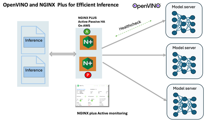
Introduction In the realm of artificial intelligence (AI) and machine learning (ML), the need for scalable and efficient AI inference solutions is paramount. As organizations deploy increasingly complex AI models to solve real-world problems, ensuring that these models can handle high volumes of inference requests becomes critical. NGINX Plus serves as a powerful ally in managing incoming traffic efficiently. As a high-performance web server and reverse proxy server, NGINX Plus is adept at load balancing and routing incoming HTTP and TCP traffic across multiple instances of AI model serving environments. The OpenVINO Model Server, powered by Intel's OpenVINO toolkit, is a versatile inference server supporting various deep learning frameworks and hardware acceleration technologies. It allows developers to deploy and serve AI models efficiently, optimizing performance and resource utilization. When combined with NGINX Plus capabilities, developers can create resilient and scalable AI inference solutions capable of handling high loads and ensuring high availability. Health checks allow NGINX Plus to continuously monitor the health of the upstream OVMS instances. If an OVMS instance becomes unhealthy or unresponsive, NGINX Plus can automatically route traffic away from it, ensuring that inference requests are processed only by healthy OVMS instances. Health checks provide real-time insights into the health status of OVMS instances. Administrators can monitor key metrics such as response time, error rate, and availability, allowing them to identify and address issues proactively before they impact service performance. In this article, we'll delve into the symbiotic relationship between the OpenVINO Model Server, and NGINX Plus to construct a robust and scalable AI inference solution. We'll explore setting up the environment, configuring the model server, harnessing NGINX Plus for load balancing, and conducting testing. By the end, readers will gain insights into how to leverage Docker, the OpenVINO Model Server, and NGINX Plus to build scalable AI inference systems tailored to their specific needs. Flow explanation: Now, let's walk through the flow of a typical inference request. When a user submits an image of a zebra for inference, the request first hits the NGINX load balancer. The load balancer then forwards the request to one of the available OpenVINO Model Server containers, distributing the workload evenly across multiple containers. The selected container processes the image using the optimized deep-learning model and returns the inference results to the user. In this case, the object is named zebra. OpenVINO™ Model Server is a scalable, high-performance solution for serving machine learning models optimized for Intel® architectures. The server provides an inference service via gRPC, REST API, or C API -- making it easy to deploy new algorithms and AI experiments. You can visit https://hub.docker.com/u/openvino for reference. Setting up: We'll begin by deploying model servers within containers. For this use case, I'm deploying the model server on a virtual machine (VM). Let's outline the steps to accomplish this: Get the docker image for OpenVINO ONNX run time docker pull openvino/onnxruntime_ep_ubuntu20 You can also visit https://docs.openvino.ai/nightly/ovms_docs_deploying_server.html for OpenVINO model server deployment in a container environment. Begin by creating a docker-compose file following the structure below: https://raw.githubusercontent.com/f5businessdevelopment/F5openVino/main/docker-compose.yml version: '3' services: resnet1: image: openvino/model_server:latest command: > --model_name=resnet --model_path=/models/resnet50 --layout=NHWC:NCHW --port=9001 volumes: - ./models:/models ports: - "9001:9001" resnet2: image: openvino/model_server:latest command: > --model_name=resnet --model_path=/models/resnet50 --layout=NHWC:NCHW --port=9002 volumes: - ./models:/models ports: - "9002:9002" # Add more services for additional containers resnet3: image: openvino/model_server:latest command: > --model_name=resnet --model_path=/models/resnet50 --layout=NHWC:NCHW --port=9003 volumes: - ./models:/models ports: - "9003:9003" resnet4: image: openvino/model_server:latest command: > --model_name=resnet --model_path=/models/resnet50 --layout=NHWC:NCHW --port=9004 volumes: - ./models:/models ports: - "9004:9004" resnet5: image: openvino/model_server:latest command: > --model_name=resnet --model_path=/models/resnet50 --layout=NHWC:NCHW --port=9005 volumes: - ./models:/models ports: - "9005:9005" resnet6: image: openvino/model_server:latest command: > --model_name=resnet --model_path=/models/resnet50 --layout=NHWC:NCHW --port=9006 volumes: - ./models:/models ports: - "9006:9006" resnet7: image: openvino/model_server:latest command: > --model_name=resnet --model_path=/models/resnet50 --layout=NHWC:NCHW --port=9007 volumes: - ./models:/models ports: - "9007:9007" resnet8: image: openvino/model_server:latest command: > --model_name=resnet --model_path=/models/resnet50 --layout=NHWC:NCHW --port=9008 volumes: - ./models:/models ports: - "9008:9008" Make sure you have Docker and Docker Compose installed on your system. Place your model files in the `./models/resnet50` directory on your local machine. Save the provided Docker Compose configuration to a file named `docker-compose.yml`. Run the following command in the directory containing the `docker-compose.yml` file to start the services: docker-compose up -d You can now access the OpenVINO Model Server instances using the specified ports (e.g., `http://localhost:9001` for `resnet1` and `http://localhost:9002` for `resnet2`). - Ensure that the model files are correctly placed in the `./models/resnet50` directory before starting the services. Set up an NGINX Plus proxy server. You can refer to https://docs.nginx.com/nginx/admin-guide/installing-nginx/installing-nginx-plus/ for NGINX Plus installation also You have the option to configure VMs with NGINX Plus on AWS by either: Utilizing the link provided below, which guides you through setting up NGINX Plus on AWS via the AWS Marketplace: NGINX Plus on AWS Marketplace or Following the instructions available on GitHub at the provided repository link. This repository facilitates spinning up VMs using Terraform on AWS and deploying VMs with NGINX Plus under the GitHub repository - F5 OpenVINO The NGINX Plus proxy server functions as a proxy for upstream model servers. Within the upstream block, backend servers (model_servers) are defined along with their respective IP addresses and ports. In the server block, NGINX listens on port 80 to handle incoming HTTP/2 requests targeting the specified server name or IP address. Requests directed to the root location (/) are then forwarded to the upstream model servers utilizing the gRPC protocol. The proxy_set_header directives are employed to maintain client information integrity while passing requests to the backend servers. Ensure to adjust the IP addresses, ports, and server names according to your specific setup. Here is an example configuration that is also available at GitHubhttps://github.com/f5businessdevelopment/F5openVino upstream model_servers { server 172.17.0.1:9001; server 172.17.0.1:9002; server 172.17.0.1:9003; server 172.17.0.1:9004; server 172.17.0.1:9005; server 172.17.0.1:9006; server 172.17.0.1:9007; server 172.17.0.1:9008; zone model_servers 64k; } server { listen 80 http2; server_name 10.0.0.19; # Replace with your domain or public IP location / { grpc_pass grpc://model_servers; health_check type=grpc grpc_status=12; # 12=unimplemented proxy_set_header Host $host; proxy_set_header X-Real-IP $remote_addr; proxy_set_header X-Forwarded-For $proxy_add_x_forwarded_for; } } If you are using gRPC with SSL please refer to the detailed configuration at NGINX Plus SSL Configuration Here is the explanation: upstream model_servers { server 172.17.0.1:9001; # Docker bridge network IP and port for your container server 172.17.0.1:9002; # Docker bridge network IP and port for your container .... .... } This section defines an upstream block named model_servers, which represents a group of backend servers. In this case, there are two backend servers defined, each with its IP address and port. These servers are typically the endpoints that NGINX will proxy requests to. server { listen 80 http2; server_name 10.1.1.7; # Replace with your domain or public IP This part starts with the main server block. It specifies that NGINX should listen for incoming connections on port 80 using the HTTP/2 protocol (http2), and it binds the server to the IP address 10.1.1.7. Replace this IP address with your domain name or public IP address. location / { grpc_pass grpc://model_servers; health_check type=grpc grpc_status=12; # 12=unimplemented proxy_set_header Host $host; proxy_set_header X-Real-IP $remote_addr; proxy_set_header X-Forwarded-For $proxy_add_x_forwarded_for; } Within the location/block, NGINX defines how to handle requests to the root location. In this case, it's using gRPC (grpc_pass grpc://model_servers;) to pass the requests to the upstream servers defined in the model_servers block. The proxy_set_header directives are used to set headers that preserve client information when passing requests to the backend servers. These headers include Host, X-Real-IP, and X-Forwarded-For. Health checks with type=grpc enable granular monitoring of individual gRPC services and endpoints. You can verify the health of specific gRPC methods or functionalities, ensuring each service component is functioning correctly. In summary, this NGINX configuration sets up a reverse proxy server that listens for HTTP/2 requests on port 80 and forwards them to backend servers (model_servers) using the gRPC protocol. It's commonly used for load balancing or routing requests to multiple backend servers. Inference Testing: This is how you can conduct testing. On the client side, we utilize a script named predict.py. Below is the script for reference # Import necessary libraries import numpy as np from classes import imagenet_classes from ovmsclient import make_grpc_client # Create a gRPC client to communicate with the server # Replace "10.1.1.7:80" with the IP address and port of your server client = make_grpc_client("10.1.1.7:80") # Open the image file "zebra.jpeg" in binary read mode with open("zebra.jpeg", "rb") as f: img = f.read() # Send the image data to the server for prediction using the "resnet" model output = client.predict({"0": img}, "resnet") # Extract the index of the predicted class with the highest probability result_index = np.argmax(output[0]) # Print the predicted class label using the imagenet_classes dictionary print(imagenet_classes[result_index]) This script imports necessary libraries, establishes a connection to the server at the specified IP address and port, reads an image file named "zebra.jpeg," sends the image data to the server for prediction using the "resnet" model, retrieves the predicted class index with the highest probability, and prints the corresponding class label. Results: Execute the following command from the client machine. Here, we are transmitting this image of Zebra to the model server. python3 predict.py zebra.jpg #run the Inference traffic zebra. The prediction output is 'zebra'. Let's now examine the NGINX Plus logs cat /var/log/nginx/access.log 10.1.1.7 - - [13/Apr/2024:00:18:52 +0000] "POST /tensorflow.serving.PredictionService/Predict HTTP/2.0" 200 4033 "-" "grpc-python/1.62.1 grpc-c/39.0.0 (linux; chttp2)" This log entry shows that a POST request was made to the NGINX server at the specified timestamp, and the server responded with a success status code (200). The request was made using gRPC, as indicated by the user agent string. Conclusion: Using NGINX Plus, organizations can achieve a scalable and efficient AI inference solution. NGINX Plus can address disruptions caused by connection timeouts/errors, sudden spikes in request rates, or changes in network topology. OpenVINO Model Server optimizes model performance and inference speed, utilizing Intel hardware acceleration for enhanced efficiency. NGINX Plus acts as a high-performance load balancer, distributing incoming requests across multiple model server instances for improved scalability and reliability. Together, this enables seamless scaling of AI inference workloads, ensuring optimal performance and resource utilization. You can look at this video for reference: https://youtu.be/Sd99woO9FmQ References: https://hub.docker.com/u/openvino https://docs.nginx.com/nginx/deployment-guides/amazon-web-services/high-availability-keepalived/ https://www.nginx.com/blog/nginx-1-13-10-grpc/ https://github.com/f5businessdevelopment/F5openVino.git https://docs.openvino.ai/nightly/ovms_docs_deploying_server.html323Views0likes0Comments