Scalable AI Deployment: Harnessing OpenVINO and NGINX Plus for Efficient Inference
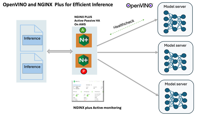
Introduction In the realm of artificial intelligence (AI) and machine learning (ML), the need for scalable and efficient AI inference solutions is paramount. As organizations deploy increasingly complex AI models to solve real-world problems, ensuring that these models can handle high volumes of inference requests becomes critical. NGINX Plus serves as a powerful ally in managing incoming traffic efficiently. As a high-performance web server and reverse proxy server, NGINX Plus is adept at load balancing and routing incoming HTTP and TCP traffic across multiple instances of AI model serving environments. The OpenVINO Model Server, powered by Intel's OpenVINO toolkit, is a versatile inference server supporting various deep learning frameworks and hardware acceleration technologies. It allows developers to deploy and serve AI models efficiently, optimizing performance and resource utilization. When combined with NGINX Plus capabilities, developers can create resilient and scalable AI inference solutions capable of handling high loads and ensuring high availability. Health checks allow NGINX Plus to continuously monitor the health of the upstream OVMS instances. If an OVMS instance becomes unhealthy or unresponsive, NGINX Plus can automatically route traffic away from it, ensuring that inference requests are processed only by healthy OVMS instances. Health checks provide real-time insights into the health status of OVMS instances. Administrators can monitor key metrics such as response time, error rate, and availability, allowing them to identify and address issues proactively before they impact service performance. In this article, we'll delve into the symbiotic relationship between the OpenVINO Model Server, and NGINX Plus to construct a robust and scalable AI inference solution. We'll explore setting up the environment, configuring the model server, harnessing NGINX Plus for load balancing, and conducting testing. By the end, readers will gain insights into how to leverage Docker, the OpenVINO Model Server, and NGINX Plus to build scalable AI inference systems tailored to their specific needs. Flow explanation: Now, let's walk through the flow of a typical inference request. When a user submits an image of a zebra for inference, the request first hits the NGINX load balancer. The load balancer then forwards the request to one of the available OpenVINO Model Server containers, distributing the workload evenly across multiple containers. The selected container processes the image using the optimized deep-learning model and returns the inference results to the user. In this case, the object is named zebra. OpenVINO™ Model Server is a scalable, high-performance solution for serving machine learning models optimized for Intel® architectures. The server provides an inference service via gRPC, REST API, or C API -- making it easy to deploy new algorithms and AI experiments. You can visit https://hub.docker.com/u/openvino for reference. Setting up: We'll begin by deploying model servers within containers. For this use case, I'm deploying the model server on a virtual machine (VM). Let's outline the steps to accomplish this: Get the docker image for OpenVINO ONNX run time docker pull openvino/onnxruntime_ep_ubuntu20 You can also visit https://docs.openvino.ai/nightly/ovms_docs_deploying_server.html for OpenVINO model server deployment in a container environment. Begin by creating a docker-compose file following the structure below: https://raw.githubusercontent.com/f5businessdevelopment/F5openVino/main/docker-compose.yml version: '3' services: resnet1: image: openvino/model_server:latest command: > --model_name=resnet --model_path=/models/resnet50 --layout=NHWC:NCHW --port=9001 volumes: - ./models:/models ports: - "9001:9001" resnet2: image: openvino/model_server:latest command: > --model_name=resnet --model_path=/models/resnet50 --layout=NHWC:NCHW --port=9002 volumes: - ./models:/models ports: - "9002:9002" # Add more services for additional containers resnet3: image: openvino/model_server:latest command: > --model_name=resnet --model_path=/models/resnet50 --layout=NHWC:NCHW --port=9003 volumes: - ./models:/models ports: - "9003:9003" resnet4: image: openvino/model_server:latest command: > --model_name=resnet --model_path=/models/resnet50 --layout=NHWC:NCHW --port=9004 volumes: - ./models:/models ports: - "9004:9004" resnet5: image: openvino/model_server:latest command: > --model_name=resnet --model_path=/models/resnet50 --layout=NHWC:NCHW --port=9005 volumes: - ./models:/models ports: - "9005:9005" resnet6: image: openvino/model_server:latest command: > --model_name=resnet --model_path=/models/resnet50 --layout=NHWC:NCHW --port=9006 volumes: - ./models:/models ports: - "9006:9006" resnet7: image: openvino/model_server:latest command: > --model_name=resnet --model_path=/models/resnet50 --layout=NHWC:NCHW --port=9007 volumes: - ./models:/models ports: - "9007:9007" resnet8: image: openvino/model_server:latest command: > --model_name=resnet --model_path=/models/resnet50 --layout=NHWC:NCHW --port=9008 volumes: - ./models:/models ports: - "9008:9008" Make sure you have Docker and Docker Compose installed on your system. Place your model files in the `./models/resnet50` directory on your local machine. Save the provided Docker Compose configuration to a file named `docker-compose.yml`. Run the following command in the directory containing the `docker-compose.yml` file to start the services: docker-compose up -d You can now access the OpenVINO Model Server instances using the specified ports (e.g., `http://localhost:9001` for `resnet1` and `http://localhost:9002` for `resnet2`). - Ensure that the model files are correctly placed in the `./models/resnet50` directory before starting the services. Set up an NGINX Plus proxy server. You can refer to https://docs.nginx.com/nginx/admin-guide/installing-nginx/installing-nginx-plus/ for NGINX Plus installation also You have the option to configure VMs with NGINX Plus on AWS by either: Utilizing the link provided below, which guides you through setting up NGINX Plus on AWS via the AWS Marketplace: NGINX Plus on AWS Marketplace or Following the instructions available on GitHub at the provided repository link. This repository facilitates spinning up VMs using Terraform on AWS and deploying VMs with NGINX Plus under the GitHub repository - F5 OpenVINO The NGINX Plus proxy server functions as a proxy for upstream model servers. Within the upstream block, backend servers (model_servers) are defined along with their respective IP addresses and ports. In the server block, NGINX listens on port 80 to handle incoming HTTP/2 requests targeting the specified server name or IP address. Requests directed to the root location (/) are then forwarded to the upstream model servers utilizing the gRPC protocol. The proxy_set_header directives are employed to maintain client information integrity while passing requests to the backend servers. Ensure to adjust the IP addresses, ports, and server names according to your specific setup. Here is an example configuration that is also available at GitHubhttps://github.com/f5businessdevelopment/F5openVino upstream model_servers { server 172.17.0.1:9001; server 172.17.0.1:9002; server 172.17.0.1:9003; server 172.17.0.1:9004; server 172.17.0.1:9005; server 172.17.0.1:9006; server 172.17.0.1:9007; server 172.17.0.1:9008; zone model_servers 64k; } server { listen 80 http2; server_name 10.0.0.19; # Replace with your domain or public IP location / { grpc_pass grpc://model_servers; health_check type=grpc grpc_status=12; # 12=unimplemented proxy_set_header Host $host; proxy_set_header X-Real-IP $remote_addr; proxy_set_header X-Forwarded-For $proxy_add_x_forwarded_for; } } If you are using gRPC with SSL please refer to the detailed configuration at NGINX Plus SSL Configuration Here is the explanation: upstream model_servers { server 172.17.0.1:9001; # Docker bridge network IP and port for your container server 172.17.0.1:9002; # Docker bridge network IP and port for your container .... .... } This section defines an upstream block named model_servers, which represents a group of backend servers. In this case, there are two backend servers defined, each with its IP address and port. These servers are typically the endpoints that NGINX will proxy requests to. server { listen 80 http2; server_name 10.1.1.7; # Replace with your domain or public IP This part starts with the main server block. It specifies that NGINX should listen for incoming connections on port 80 using the HTTP/2 protocol (http2), and it binds the server to the IP address 10.1.1.7. Replace this IP address with your domain name or public IP address. location / { grpc_pass grpc://model_servers; health_check type=grpc grpc_status=12; # 12=unimplemented proxy_set_header Host $host; proxy_set_header X-Real-IP $remote_addr; proxy_set_header X-Forwarded-For $proxy_add_x_forwarded_for; } Within the location/block, NGINX defines how to handle requests to the root location. In this case, it's using gRPC (grpc_pass grpc://model_servers;) to pass the requests to the upstream servers defined in the model_servers block. The proxy_set_header directives are used to set headers that preserve client information when passing requests to the backend servers. These headers include Host, X-Real-IP, and X-Forwarded-For. Health checks with type=grpc enable granular monitoring of individual gRPC services and endpoints. You can verify the health of specific gRPC methods or functionalities, ensuring each service component is functioning correctly. In summary, this NGINX configuration sets up a reverse proxy server that listens for HTTP/2 requests on port 80 and forwards them to backend servers (model_servers) using the gRPC protocol. It's commonly used for load balancing or routing requests to multiple backend servers. Inference Testing: This is how you can conduct testing. On the client side, we utilize a script named predict.py. Below is the script for reference # Import necessary libraries import numpy as np from classes import imagenet_classes from ovmsclient import make_grpc_client # Create a gRPC client to communicate with the server # Replace "10.1.1.7:80" with the IP address and port of your server client = make_grpc_client("10.1.1.7:80") # Open the image file "zebra.jpeg" in binary read mode with open("zebra.jpeg", "rb") as f: img = f.read() # Send the image data to the server for prediction using the "resnet" model output = client.predict({"0": img}, "resnet") # Extract the index of the predicted class with the highest probability result_index = np.argmax(output[0]) # Print the predicted class label using the imagenet_classes dictionary print(imagenet_classes[result_index]) This script imports necessary libraries, establishes a connection to the server at the specified IP address and port, reads an image file named "zebra.jpeg," sends the image data to the server for prediction using the "resnet" model, retrieves the predicted class index with the highest probability, and prints the corresponding class label. Results: Execute the following command from the client machine. Here, we are transmitting this image of Zebra to the model server. python3 predict.py zebra.jpg #run the Inference traffic zebra. The prediction output is 'zebra'. Let's now examine the NGINX Plus logs cat /var/log/nginx/access.log 10.1.1.7 - - [13/Apr/2024:00:18:52 +0000] "POST /tensorflow.serving.PredictionService/Predict HTTP/2.0" 200 4033 "-" "grpc-python/1.62.1 grpc-c/39.0.0 (linux; chttp2)" This log entry shows that a POST request was made to the NGINX server at the specified timestamp, and the server responded with a success status code (200). The request was made using gRPC, as indicated by the user agent string. Conclusion: Using NGINX Plus, organizations can achieve a scalable and efficient AI inference solution. NGINX Plus can address disruptions caused by connection timeouts/errors, sudden spikes in request rates, or changes in network topology. OpenVINO Model Server optimizes model performance and inference speed, utilizing Intel hardware acceleration for enhanced efficiency. NGINX Plus acts as a high-performance load balancer, distributing incoming requests across multiple model server instances for improved scalability and reliability. Together, this enables seamless scaling of AI inference workloads, ensuring optimal performance and resource utilization. You can look at this video for reference: https://youtu.be/Sd99woO9FmQ References: https://hub.docker.com/u/openvino https://docs.nginx.com/nginx/deployment-guides/amazon-web-services/high-availability-keepalived/ https://www.nginx.com/blog/nginx-1-13-10-grpc/ https://github.com/f5businessdevelopment/F5openVino.git https://docs.openvino.ai/nightly/ovms_docs_deploying_server.html287Views0likes0CommentsDistributed Cloud Support for NAS Migrations from On-Premises Approaches to Azure NetApp Files
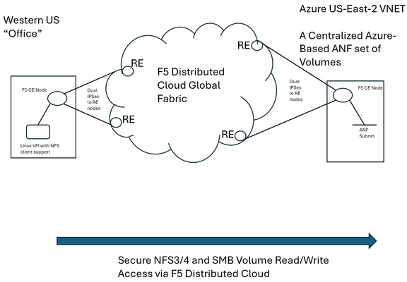
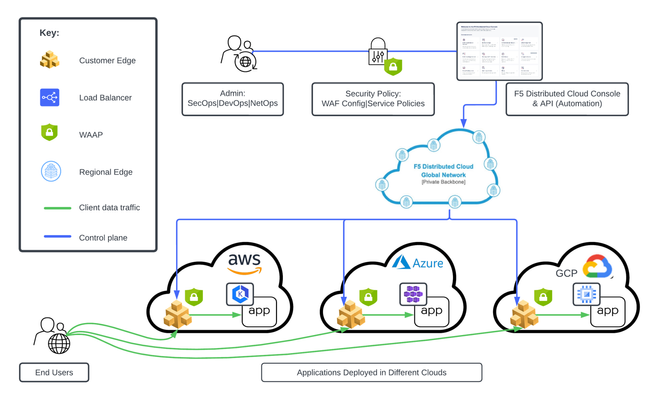
F5 Distributed Cloud (XC) Secure Multicloud Networking (MCN) connects and secures distributed applications across offices, data centers, and various cloud platforms. Frequently the technology is web-based, meaning traffic is often carried on ports like TCP port 443, however other traffic types are also prevalent in an enterprise’s traffic mix. Examples include SSH or relational database protocols. One major component of networked traffic is Network-Attached Storage (NAS), a protocol in the past frequently carried over LANs between employees in offices and co-located NAS appliances, perhaps in wiring closets or server rooms. An example of such an appliance would be the ONTAP family from NetApp which can take on physical or virtual form factors. NAS protocols are particularly useful as they integrate file stores into operating systems such as Microsoft Windows or Linux distributions as directories, mounted for easy access to files at any time, often permanently. This contrasts with SSH file transfers, which are often ephemeral actions and not so tightly integral to host operating system health. With the rise of remote work, often the NAS appliances see increasing file reads-and-writes to these directories, traversing wide-area links. In fact, one study analyzing fundamental traffic changes due to the Covid-19 pandemic saw a 22 percent increase in file transfer protocol (FTP) in a single year, suggesting access to files has undergone significant foundational changes in recent years. Distributed Cloud and the Movement towards Centralized Enterprise Storage A traditional concern about serving NAS files to offices from a centralized point, such as a cloud-instantiated file repository, is latency and reliability. With F5’s Distributed Cloud offering a 12 Tbps aggregate backbone and dedicated RE-to-RE links, the behavior of the network component is both highly durable and performant. The efficiencies of a centralized corporate file distribution point, with the required 9’s of guaranteed uptime of modern cloud services, and the logic of moving towards cloud-served NAS solutions makes a lot of sense. With on-premises storage appliances replaced by a secure, networked service eliminates the need to maintain costly spares, which are effectively a shadow NAS appliance infrastructure and onerous RMA procedures. All of this enables accomplishing the goal of shrinking/greening office wiring closets. To demonstrate this centralized model for a NAS architecture, a configuration was created whereby a west coast simulated office was connected by F5 Distributed Cloud to Azure NetApp Files (ANF) instantiated in Azure East-2 region. ANF is Microsoft Azure’s newest native file serving solution, managed by NetApp, with data throughputs that increase in lock step with the amount of reserved storage pool capacity. Different quality of service (QoS) levels are selectable by the consumer. In the streamlined ANF configuration workflow, where various transaction latency thresholds may be requested, even the most demanding relational database operations are typically accommodated. Microsoft offers additional details on ANF here, however, this article should serve to sufficiently demonstrate the ANF and F5 Distributed Cloud Secure MCN solutions for most readers. Distributed Cloud and Azure NetApp Files Deployment Example NAS in the enterprise today largely involves use of either NFS or SMB protocols, both of which can be used within Windows and Linux environments and make remote directories appear and perform as if local to users. In our example, a western US point of presence was leveraged to serve as the simulated remote office and standard Linux hosts to serve as the consumers of NetApp volumes. In the east, a corporate VNET was deployed in an Azure resource group (RG) in US-East-2, with one subnet delegated to provide Azure NetApp Files (ANF). To securely connect the west coast office to the eastern Azure ANF service, F5 Distributed Cloud Secure MCN was utilized to create a Layer 3 multi-cloud network offering. This is achieved by easily dropping an F5 customer edge (CE) virtual appliance into both the office and the Azure VNET in the east. The CE is a 2-port security appliance. The inside interfaces on both CEs were attached to a global virtual network, and exclusive layer-3 associations to allow simple connectivity and fully preserve privacy. In keeping with the promise of SaaS, Distributed Cloud users require no routing protocol setup. The solution takes care of the control plane, including routing and encryption. This concept could be scaled to hundreds of offices, if equipped with CEs, and easily attached to the same global virtual network. CEs, at boot-up, automatically attach via IP Sec (or SSL) tunnels to geographically close F5 backbone nodes, called regional edge (RE) sites. Like tunnel establishment, routing tables are updated under-the-hood to allow for a turn-key security relationship between Azure NetApp File volumes and consuming offices. The setup is depicted as follows: Setup Azure NetApp Files (ANF) Volumes in Minutes To put the centralized approach to offering NAS volumes for remote offices or locations into practice, a series of quick steps are undertaken, which can all be done through the standard Microsoft Azure portal. The four steps are listed below, with screenshots provided for key points in the brief process: If not starting from an existing Resource Group (RG), create a new RG and add an Azure VNET to it. Delegate one subnet in your VNET to support ANF. Under “Delegate Subnet to a Service” select from the pull-down-list the entry “Microsoft.NetApp/volumes”. Within the Resource Group, choose “Create” and make a NetApp account. This will appear in the Azure Marketplace listings as “Azure NetApp Files”. In your NetApp account, under “Storage service” create a capacity pool. The pool should be sized appropriately, larger is typically better, since numerous volumes, supporting your choice of NFS3/4 and SMB protocols, will be created from this single, large disk pool. Create your first volume, select size, NAS protocols to support, and QoS parameters that meet your business requirements. As seen below, when adding a capacity pool simply follow the numerical sequence to add your pool, with a newly created sample 2 TiB pool highlighted; 1,024 TiB (1 PiB) are possible (click image to enlarge). Interestingly, the capacity pool shown is the “Standard” service level, as opposed to “Premium” and “Ultra”. With QoS type of Auto selected, Azure NetApp Files provides increasing throughput in terms of megabytes per second as the number of TiB in the pool increases. The throughput also increases with service levels; for standard, as shown, 8 megabytes per second per TiB will be allocated. Beyond throughput, ANF also provides the lowest latency averages for reads and writes in the Azure portfolio of storage offerings. As such, ANF is a very good fit for database deployments that must see constrained, average latency for mission-critical transactions. Deeper discussion around ANF service levels may be explored through the Microsoft document here. The next screenshot shows the simple click-through sequence for adding a volume to the capacity pool, simply click on volumes and the “+Add volume” button. A resulting sample volume is displayed in the figure with key parameters highlighted. In the above volume (“f5-distributed-cloud-vol-001”) the NAS protocol selected was NFSv3 and the size of the volume (“Quota”) was set to 100GiB. Setup F5 Distributed Cloud Office-to-Azure Connectivity To access the volume in a secured and highly responsive manner, from corporate headquarters, remote offices or existing data centers, three items from F5 Distributed Cloud are required: A customer edge (CE) node, normally with 2-ports, must be deployed in the Azure RG VNET. This establishes the Azure instance as a “site” within the Distributed Cloud dashboard. Hub and spoke architectures may also be used if required, where VNET peering can also allow the secure multi-cloud network (MCN) solution to operate seamlessly. A CE is deployed at a remote office or datacenter, where file storage services are required by various lines of business. The CE is frequently deployed as a virtual appliance or installed on a bare metal server and typically has 2-ports. To instantiate a layer-3 MCN service, the inside ports of the two CEs are “joined” to a virtual global network created by the enterprise in the Distributed Cloud console, although REST API and Terraform are also deployment options. By having each inside port of the Azure and office CE’s joined to the same virtual network, the “inside” subnets can now communicate with each other, securely, with traffic normally exchanged over encrypted high-speed IPSec tunnels into the F5 XC global fabric. The following screenshot demonstrates adding the Azure CE inside interface to a global virtual network, allowing MCN connectivity to remote office clients requiring access to volumes. Further restrictions, to prevent unauthorized clients, are found within NAS protocols themselves, such as simple Export policies in NFS and ACL rules in SMB/CIFS, which can be configured quickly within ANF. Remote Office Access – Establish Read/Write File Access to Azure ANF over F5 Distributed Cloud With both ANF configured and F5 Distributed Cloud now providing a layer-3 muticloud network (MCN) solution, to patch enterprise offices to the centralized storage, some confirmation of the solution working as expected was desired. First off, a choice in protocols was made. When configuring ANF, the normal choices for access are NFSv3/v4 or SMB/CIFS or both protocols concurrently. Historically, Microsoft hosts made use of SMB/CIFS and Linux/Unix hosts preferred NFS, however today both protocols are used throughout enterprises. One example being long-time SAMBA server (SMB/CIFS) support in the world of Linux. Azure NetApp Files will provide all the necessary command samples to get hosts connected without difficulty. For instance, to mount the volume to a folder off the Linux user home directory, such as the sample folder “f5-distributed-cloud-vol-001”, per the ANF suggestion the following one command will connect the office Linux host to the central storage in Azure-East-2: sudo mount -t nfs -o rw,hard,rsize=262144,wsize=262144,vers=3,tcp 10.0.9.4:/f5-distributed-cloud-vol-001 f5-distributed-cloud-vol-001 At this point the volume is available for day-to-day tasks, including read and write operations, as if the NAS solution were local to the office, often literally down the hallway. Remote Office Access - Demonstration of Azure ANF over F5 Distributed Cloud i zThe following sample wrote a file of 20,000 bytes to the ANF service, waited a few seconds, and then removed the file before beginning another cycle. At the lowest common denominator, packet analysis for the ensuing traffic from the western US office will indicate both network and application latency sample values. As depicted in the following Wireshark trace, the TCP response to a transmitted segment carrying an NFS command, was observed to be just 74.5 milliseconds. This prompt round-trip latency for a cross-continent data plane suggests a performant Distributed Cloud MCN service level. This is easily seen as the offset from the reference timestamp (time equal to zero) of the NFS v3 Create Call. Click on image to expand. Analyzing the NAS response from ANF (packet 185) arrives less than 1 millisecond later, suggesting a very responsive, well-tuned NFS control plane offered by ANF. To measure the actual, write-time of a file from west coast to east coast, the following trace demonstrates the 20,000 byte file write exercise from the shell script. In this case, the TCP segments making up the file, specifically the large packet body lengths called out in the screenshot, are delivered efficiently without TCP retransmissions, TCP zero window events, nor having any indicators of layer 3 and 4 health concerns. The entirety of the write is measured at the packet layer to take only 150.8 milliseconds. Since packet-level analysis is not the most turnkey, easy method to monitor file read and write performance, a set of Linux and Windows utilities can also be leveraged. The Linux utility nfsiostat was concurrently used with the test file writes and produced similar, good latency measurements. Nfsiostat monitoring of the file write testing, from west coast to east coast, for the 20,000-byte file, has indicated an average write time to ANF of 151 milliseconds. The measurements presented here are simply observational, to present rapid, digestible techniques for readers interested in service assurance for running ANF over an XC L3 MCN offering. For more rigorous monitoring treatments, Microsoft provides guidance on performing one’s own measurements of Azure NetApp Files here. Summary As enterprise-class customers continue to rapidly look towards cloud for compute performance, GPU access, and economies-of-scale savings for key workloads, the benefits of a centralized, scalable storage counterpart to this story exists. F5 Distributed Cloud offers the reach and performance levels to securely tie existing offices and data centers to cloud-native storage solutions. One example of this approach to modernize storage was covered in this article, the turn-key ability to begin transitioning from traditionally on-premises NAS appliances to cloud-native scalable volumes. The Azure NetApp Files approach to serving read/write volumes allows modern hosts, including Windows and Linux distributions, to utilize virtually unlimited folder sizes with service levels adjustable to business needs.70Views0likes1CommentSolving for true-source IP with global load balancers in Google Cloud
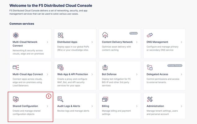
Background Recently a customer approached us with requirements that may seem contradictory: true source IP persistence, global distribution of load balancers (LB's), TCP-only proxying, and alias IP ranges in Google Cloud. With the help of PROXY protocol support, we offered a straightforward solution that is worth documenting for others. Customer requirements We have NGINX WAF running on VM instances in Google Cloud Platform (GCP) We want to expose these to the Internet with aglobal load balancer We must know the true source IP of clients when traffic reaches our WAF We donot want so use an application (HTTP/S) load balancer in Google. i.e., we do not want to perform TLS decryption with GCP or use HTTP/HTTPS load balancing therefore, we cannot use X-Forwarded-For headers to preserve true source IP Additionally, we'd like to use Cloud Armor. How can we add on a CDN/DDoS/etc provider if needed? Let's solve for these requirements by finding the load balancer to use, and then how to preserve and use true source IP. Which load balancer type fits best? This guideoutlines our options for Google LB’s. Because our requirements includeglobal, TCP-only load balancing, we will choose the highlighted LB type of “Global external proxy Network Load Balancer”. Proxy vs Passthrough Notice that global LB’sproxytraffic. They do not preserve source IP address as apassthrough LB does. Global IP addresses are advertised from multiple, globally-distributed front end locations, using Anycast IP routing. Proxying from these locations allows traffic symmetry, but Source NAT causes loss of the original client IP address. I've added some comments into a Google diagram below to show our core problem here: PROXY protocol support with Google load balancers Google’s TCP LBdocumentationoutlines our challenge and solution: "By default, the target proxy does not preserve the original client IP address and port information. You can preserve this information by enabling the PROXY protocol on the target proxy." Without PROXY protocol support, we could only meet 2 out of 3 core requirements with any given load balancer type. PROXY protocol allows us to meet all 3 simultaneously. Setting up our environment in Google The script below configures a global TCP proxy network load balancer and associated objects. It is assumed that a VPC network, subnet, and VM instances exist already. This script assumes the VM’s are F5 BIG-IP devices, although our demo will use Ubuntu VM’s with NGINX installed. Both BIG-IP and NGINX can easily receive and parse PROXY protocol. # GCP Environment Setup Guide for Global TCP Proxy LB with Proxy Protocol. Credit to Tony Marfil, @tmarfil # Step 1: Prerequisites # Before creating the network endpoint group, ensure the following GCP resources are already configured: # # -A VPC network named my-vpc. # -A subnet within this network named outside. # -Instances ubuntu1 and ubuntu2 should have alias IP addresses configured: 10.1.2.16 and 10.1.2.17, respectively, both using port 80 and 443. # # Now, create a network endpoint group f5-neg1 in the us-east4-c zone with the default port 443. gcloud compute network-endpoint-groups create f5-neg1 \ --zone=us-east4-c \ --network=my-vpc \ --subnet=outside \ --default-port=443 # Step 2: Update the Network Endpoint Group # # Add two instances with specified IPs to the f5-neg1 group. gcloud compute network-endpoint-groups update f5-neg1 \ --zone=us-east4-c \ --add-endpoint 'instance=ubuntu1,ip=10.1.2.16,port=443' \ --add-endpoint 'instance=ubuntu2,ip=10.1.2.17,port=443' # Step 3: Create a Health Check # # Set up an HTTP health check f5-healthcheck1 that uses the serving port. gcloud compute health-checks create http f5-healthcheck1 \ --use-serving-port # Step 4: Create a Backend Service # # Configure a global backend service f5-backendservice1 with TCP protocol and attach the earlier health check. gcloud compute backend-services create f5-backendservice1 \ --global \ --health-checks=f5-healthcheck1 \ --protocol=TCP # Step 5: Add Backend to the Backend Service # # Link the network endpoint group f5-neg1 to the backend service. gcloud compute backend-services add-backend f5-backendservice1 \ --global \ --network-endpoint-group=f5-neg1 \ --network-endpoint-group-zone=us-east4-c \ --balancing-mode=CONNECTION \ --max-connections=1000 # Step 6: Create a Target TCP Proxy # # Create a global target TCP proxy f5-tcpproxy1 to handle routing to f5-backendservice1. gcloud compute target-tcp-proxies create f5-tcpproxy1 \ --backend-service=f5-backendservice1 \ --proxy-header=PROXY_V1 \ --global # Step 7: Create a Forwarding Rule # # Establish global forwarding rules for TCP traffic on port 80 & 443. gcloud compute forwarding-rules create f5-tcp-forwardingrule1 \ --ip-protocol TCP \ --ports=80 \ --global \ --target-tcp-proxy=f5-tcpproxy1 gcloud compute forwarding-rules create f5-tcp-forwardingrule2 \ --ip-protocol TCP \ --ports=443 \ --global \ --target-tcp-proxy=f5-tcpproxy1 # Step 8: Create a Firewall Rule # # Allow ingress traffic on specific ports for health checks with the rule allow-lb-health-checks. gcloud compute firewall-rules create allow-lb-health-checks \ --direction=INGRESS \ --priority=1000 \ --network=my-vpc \ --action=ALLOW \ --rules=tcp:80,tcp:443,tcp:8080,icmp \ --source-ranges=35.191.0.0/16,130.211.0.0/22 \ --target-tags=allow-health-checks # Step 9: Add Tags to Instances # # Tag instances ubuntu1 and ubuntu2 to include them in health checks. gcloud compute instances add-tags ubuntu1 --tags=allow-health-checks --zone=us-east4-c gcloud compute instances add-tags ubuntu2 --tags=allow-health-checks --zone=us-east4-c ## TO PULL THIS ALL DOWN: (uncomment the lines below) # gcloud compute firewall-rules delete allow-lb-health-checks --quiet # gcloud compute forwarding-rules delete f5-tcp-forwardingrule1 --global --quiet # gcloud compute forwarding-rules delete f5-tcp-forwardingrule2 --global --quiet # gcloud compute target-tcp-proxies delete f5-tcpproxy1 --global --quiet # gcloud compute backend-services delete f5-backendservice1 --global --quiet # gcloud compute health-checks delete f5-healthcheck1 --quiet # gcloud compute network-endpoint-groups delete f5-neg1 --zone=us-east4-c --quiet # # Then delete your VM's and VPC network if desired. Receiving PROXY protocol using NGINX We now have 2x Ubuntu VM's running in GCP that will receive traffic when we target our global TCP proxy LB's IP address. Let’s use NGINX to receive and parse the PROXY protocol traffic. When proxying and "stripping" the PROXY protocol headers from traffic, NGINX can append an additional header containing the value of the source IP obtained from PROXY protocol: server { listen 80 proxy_protocol; # tell NGINX to expect traffic with PROXY protocol server_name customer1.my-f5.com; location / { proxy_pass http://localhost:3000; proxy_http_version 1.1; proxy_set_header x-nginx-ip $server_addr; # append a header to pass the IP address of the NGINX server proxy_set_header x-proxy-protocol-source-ip $proxy_protocol_addr; # append a header to pass the src IP address obtained from PROXY protocol proxy_set_header Host $host; proxy_set_header X-Real-IP $remote_addr; # append a header to pass the src IP of the connection between Google's front end LB and NGINX proxy_cache_bypass $http_upgrade; } } Displaying true source IP in our web app You might notice above that NGINX is proxying to http://localhost:3000. I have a simple NodeJS app to display a page with HTTP headers: const express = require('express'); const app = express(); const port = 3000; // set the view engine to ejs app.set('view engine', 'ejs'); app.get('/', (req, res) => { const proxy_protocol_addr = req.headers['x-proxy-protocol-source-ip']; const source_ip_addr = req.headers['x-real-ip']; const array_headers = JSON.stringify(req.headers, null, 2); const nginx_ip_addr = req.headers['x-nginx-ip']; res.render('index', { proxy_protocol_addr: proxy_protocol_addr, source_ip_addr: source_ip_addr, array_headers: array_headers, nginx_ip_addr: nginx_ip_addr }); }) app.listen(port, () => { console.log('Server is listenting on port 3000'); }) For completeness, NodeJS is using the EJS template engine to build our page. The file views/index.ejs is here: <!DOCTYPE html> <html lang="en"> <head> <meta charset="UTF-8"> <meta name="viewport" content="width=device-width, initial-scale-1"> <title>Demo App</title> </head> <body class="container"> <main> <h2>Hello World!</h2> <p>True source IP (the value of <code>$proxy_protocol_addr</code>) is <b><%= typeof proxy_protocol_addr != 'undefined' ? proxy_protocol_addr : '' %></b></p> <p>IP address that NGINX recieved the connection from (the value of <code>$remote_addr</code>) is <b><%= typeof source_ip_addr != 'undefined' ? source_ip_addr : '' %> </b></p> <p>IP address that NGINX is running on (the value of <code>$server_addr</code>) is <b><%= typeof nginx_ip_addr != 'undefined' ? nginx_ip_addr : '' %></b><p> <h3>Request Headers at the app:</h3> <pre><%= typeof array_headers != 'undefined' ? array_headers : '' %></pre> </main> </body> </html> Cloud Armor Cloud Armor is aneasy add-onwhen using Google load balancers. If required, an admin can: Create a Cloud Armor security policy Add rules (for example, rate limiting) to this policy Attach the policy to a TCP load balancer In this way “edge protection” is applied to your Google workloads with little effort. Our end result This small demo app shows that true source IP can be known to an application running on Google VM’s when using the Global TCP Network Load Balancer. We’ve achieved this using PROXY protocol and NGINX. We’ve used NodeJS to display a web page with proxied header values. Thanks for reading. Please reach out with any questions!205Views3likes4CommentsF5 Distributed Cloud – Multiple custom certificates for HTTP/TCP LB
TLS Certificate A TLS certificate is a digital certificate signed by a trusted Certificate Authority (CA) that will authenticate the identity of the certificate owner. It is required to encrypt and secure traffic over the internet using Public Key Infrastructure (PKI). F5 Distributed Cloud (F5 XC) had already implemented the ability to choose between automatic TLS certificate management and attaching a custom TLS certificate (aka Bring Your Own Certificate) in its HTTP/TCP load balancer configurations. Now a new feature is added enabling customers to attach multiple custom TLS certificates to a single HTTP/TCP load balancer, this will allow them to host multiple domains with different certificates from a single load balancer so that they can optimize costs or simplify configuration. Also, now TLS certificates can be shared across multiple LBs and customers can view and manage their TLS certificates and intermediate certificate chains as standalone objects from a centralized place. Note: This feature is supported for the HTTP/TCP LBs advertised either on Regional Edges (REs) or on Customer Edge (CE). Configuration Step1: Create TLS certificate object in XC console Select `Shared Configuration` service from the home page of XC console. Select `Certificate Management` from the left menu and select `TLS Certificates`, Click `Add TLS Certificate`. Note: Certificate Management configuration can be done either from Multi-Cloud App Connect, Web App & API Protection, Distributed Apps, or Shared Configuration services. Configure certificate properties and upload the certificate. Note: Supported certificate formats are PEM and PKCS#12 (aka P12) Optionally, configure OCSP stapling and intermediate certificate chain. OCSP (Online Certificate Status Protocol) is used to determine the revocation state of digital certificates. For more information on OCSP stapling follow the documentation Certificate Chain of trust refers to all the certificates that are linked together in an ordered fashion to validate the legitimacy of the server certificate. There are 3 components in this certificate chain: Root certificate: This certificate belongs to Root Certificate Authority (CA) and are self-signed. Intermediate certificate: This certificate belongs to intermediate CA and are signed by Root CA, Intermediate CA signs the certificates on behalf of Root CA and there can be one or more Intermediate CA in a certificate chain of trust. Leaf/server certificate: This certificate belongs to the web server to establish secure connection or authenticating clients reaching to the server, this can either be signed by a Root CA or an Intermediate CA. Above screenshot shows the list of TLS Certificates, one certificate is signed by the Root CA and is created in personal namespace (demo) while the other certificate is signed by the Intermediate CA and is created in `shared namespace` (Note: objects created in shared namespace can be used across all other namespaces). Step2: Attach TLS certificates to the load balancer (HTTP/TCP) Note: In this demonstration, we are attaching the TLS certificates to the HTTP LB Click on `Load Balancers`, from the left menu and select `HTTP Load Balancers`. Click Add `HTTP Load Balancer`, Configure HTTP LB, enter valid domains as per the TLS certificates. Select ‘HTTPS with Custom Certificate’ option in ‘Load Balancer Type’ field, and in ‘TLS Configuration’ select `Multiple Certificates` option. Click on ‘Configure’ and attach the above created TLS certificates by keeping ‘TLS Security Level’ as `High`. We have already created origin pools for our two domains and added those origin pool members to the LB with the help of ‘Routes’ as shown inthe screenshots below. (Applications deployed on origin servers are httpbin and dvga) You could either advertise this LB to the internet which is also a default setting or can customize it to be advertised on a CE site. For this demo we have advertised the LB to 'Internet'. Click `Save and Exit`. Note:Each LB has a certificate expiration date, and in case of multiple certs this value is automatically set to the expiry date of its certificate which is expiring earlier. Similarly, you can configure TCP LB as well with multiple custom TLS certificates. For more details on how to configure TCP LB refer to the document. Step3: Check the server certificate details by clicking padlock next to the URL Open the browser and check for the LB domains, Connection should be shown as secure. Note: In this demo we are using local domain names and TLS Certificates, so we have manually added the custom local `Root CA` certificate to the browser and edited the hosts file to map VIP with our domain names. When the certificate expiry date approaches near, you will be notified with alerts. You can see active alerts by navigating to `Notifications -> Alerts` section from the menu on the left side or by clicking the bell icon on top right corner of the XC console. Based on the alerts received, you can renew the certificate expiration date and upload it again to the existing XC’s TLS cert object to reuse it instead of creating a new object. Conclusion: In the above demo, you have seen using XC console how easy it is to manage your multiple custom TLS certificates from a centralized place.2.8KViews3likes0CommentsDeploy WAF on any Edge with F5 Distributed Cloud (SaaS Console, Automation)
F5 XC WAAP/WAF presents a clear advantage over classical WAAP/WAFs in that it can be deployed on a variety of environments without loss of functionality. In this first article of a series, we present an overview of the main deployment options for XC WAAP while follow-on articles will dive deeper into the details of the deployment procedures.5.3KViews9likes0CommentsThe App Delivery Fabric with Secure Multicloud Networking
This tutorial with accompanying workflow guide deploys customer edge sites and uses Distributed Cloud Multicloud Networking App Connect to establish a Secure MCN App Delivery Fabric, enabling only Layer7 app connectivity between two cloud sites. Manual and automation workflows show how to make this NetOps and DevOps task come to life.152Views1like0CommentsUsing Distributed Application Security Policies in Secure Multicloud Networking Customer Edge Sites
This tutorial and workflow guide deploys and uses F5 Distributed Cloud App Security policies with apps at local customer edge sites. Deploy a policy in any customer edge site regardless of location in the cloud or on-prem. Manual and automation workflows show how to make this NetOps and DevOps friendly solution come to life.219Views0likes0CommentsMaking Mobile SDK Integration Ridiculously Easy with F5 XC Mobile SDK Integrator
Introduction To prevent attackers from exploiting mobile apps to launch bots, F5 provides customers with the F5 Distributed Cloud (XC) Mobile SDK, which collects signals for the detection of bots. To gain this protection, the SDK must be integrated into mobile apps, a process F5 explains in clear step-by-step technical documentation. Now, F5 provides an even easier option, the F5 Distributed Cloud Mobile SDK Integrator, a console app that performs the integration directly into app binaries without any need for coding, which means no need for programmer resources, no need to integration delays. The Mobile SDK Integrator supports most iOS and Android native apps. As a console application, it can be tied directly into CI/CD pipelines to support rapid deployments. Use Cases While motivations for using SDK Integrator may vary, below are some of the more common reasons: Emergency integrations can be accomplished quickly and correctly. Customers experiencing active bot attacks may need to integrate with F5 Distributed Cloud Bot Defense immediately and minimize integration risks. Apps using 3rd-party libraries may not be suitable for manual integration, particularly when these libraries do not provide APIs for adding HTTP headers into network requests. In such cases, the SDK Integrator can inject SDK calls into the underlying network stack, bypassing the limitations of the network library. Customers who own multiple apps, which may have different architectures, or are managed by different owners, need a single integration method, one which works for all app architectures and is simple to roll out to multiple teams. The SDK Integrator facilitates a universal integration approach. How It Works The work of the SDK Integrator is done through two commands: the first command creates a configuration profile for the SDK injection, and the second performs the injection. Step 1: $ python3 ./create_config.py --target-os Android --apiguard-config ./base_configuration_android.json --url-filter "*.domain.com/*/login" --enable-logs --outfile my_app_android_profile.dat In Step 1, apiguard-config lets the user specify the base configuration to be used in integration. With url-filter we specify the pattern for URLs which require Bot Defense protection, enable-logs allows for APIGuard logs to be seen in the console, outfile specifies the name of this integration profile. Step 2: $ java -jar SDK-Integrator.jar --plugin F5-XC-Mobile-SDK-Integrator-Android-plugin-4.1.1-4.dat --plugin my_app_android_profile.dat ./input_app.apk --output ./output_app.apk --keystore ~/my-key.keystore --keyname mykeyname --keypass xyz123 --storepass xyz123 In Step 2, we specify which SDK Integrator plugin and configuration profile should be used. In the same step, we can optionally pass parameters for app-signing: keystore, keyname, keypass and storepass. Output parameter specifies the resulting file name. The resulting .apk or .aab file is a fully integrated app, which can be tested and released. Injection steps for iOS are similar. The commands are described in greater detail in the SDK Integrator user guides distributed with the SDK Integrator. Mobile SDK Integrator Video In Conclusion In order to thwart potential attackers from capitalizing on mobile apps to initiate automated bots, The F5 Distributed Cloud Mobile SDK Integrator seamlessly incorporates the SDK into app binaries, completely bypassing the necessity for coding making the process easy and fast. Related Content Deploy Bot Defense on any Edge with F5 Distributed Cloud (SaaS Console, Automation) Protecting Your Native Mobile Apps with F5 XC Mobile App Shield Bot Defense for Mobile Apps in XC WAAP Part 1: The Bot Defense Mobile SDK1.2KViews3likes1CommentEnabling F5 Distributed Cloud Client-Side Defense in BIG-IP 17.1
Introduction In the freshest BIG-IP release, version 17.1, we continue to expand, enrich, and streamline the realm of application security, delivery, and automation that BIG-IP platforms provide for applications.In this article we'll be zooming in on the new Distributed Cloud Client-Side Defense connectivity which enables a self-managed service that seamlessly integrates with F5 BIG-IP to protect against client-side attacks such as Magecart, digital skimming, formjacking, (PII) harvesting, and other types of browser-based supply chain attacks. New BIG-IP Distributed Cloud Services Module Immersed within this cutting-edge release we're empowering our customers with an ingenious Distributed Cloud Services Integration Module. This powerful module grants customers the ability to harness their existing BIG-IP deployments and effortlessly apply cloud-based security services to their application transactions, all from within the intuitive BIG-IP console. These remarkable security services act as a catalyst, empowering application owners and security personnel to harness the sheer might of industry-leading Bot and Fraud cloud connectors. This union allows for a seamless integration with the F5 Distributed Cloud Services, ensuring that simplicity and security are bestowed upon every aspect of this integration. XC Client-Side Defense Solution Overview In BIG-IP 17.1 Distributed Cloud Client-Side Defense connectivity enables a self-managed service that seamlessly integrates with F5 BIG-IP to protect against client-side attacks such as Magecart, digital skimming, formjacking, (PII) harvesting, and other types of browser-based supply chain attacks. By providing real-time monitoring of a web application’sJavaScript libraries for malicious activities, Distributed Cloud Client-Side Defense protects consumer data from being accessed by cybercriminals and assists organizations in meeting the new PCI DSS 4.0 requirements CSD Onboarding Demo Conclusion In conclusion, this revolutionary BIG-IP 17.1 release includes Distributed Cloud Client-Side Defense and acts as a vigilant guardian, actively monitoring the JavaScript libraries of web applications in real-time. This unwavering surveillance serves a paramount purpose—safeguarding consumer data from the clutches of malicious cybercriminals. Furthermore, this formidable defense mechanism offers invaluable assistance to organizations by aiding them in meeting the stringent demands of the new PCI DSS 4.0 requirements. With its watchful eye and unwavering commitment to security, Distributed Cloud Client-Side Defense emerges as an indispensable asset in the realm of safeguarding sensitive information. Additional Resources Deploy Bot Defense on any Edge with F5 Distributed Cloud (SaaS Console, Automation) F5 Client-Side Defense Client-Side Defense Documentation Youtube Demo - Enabling F5 Distributed Cloud Client-Side Defense in BIG-IP 17.1 Automating Deployment of F5 Distributed Cloud Client-Side Defense835Views3likes0Comments